Hydraulic Load Cells

Hydraulic Load Cells

The Hydraulic Load Cells are intended to be located at the base of reinforcement structures in order to measure the load transmitted to their base. Checks of this type are essential to guarantee the safety of temporary and permanent retaining structures. Load cells are generally installed at the foot of tunnels, below rib supports, bulkhead support struts, piles, etc, and are of a shape and size to simplify installation.

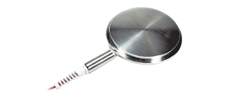
Our Hydraulic Load Cells consist of two circular steel plates, shaped and soldered together in such a way as to create an interspace which is filled with a special oil and connected to an electric transducer which converts each change of pressure on the cell into a variable electric signal with standard exit of 4 ÷ 20 mA (on request we can provide cells with vibrating wire sensor).

All sensor parts, including cables, are isolated and protected, in order to avoid concrete (or water) getting into the cell; circuits and sensors are resinated and protected in order to ensure the instrument still functions in the event of impact or immersion.

The reading of data provided by the electric pressure transducer is possible either using a portable unit or via automatic data acquisition system for continuous monitoring.

Contact us for further information

Edit

Applications

hydraulic load cells with large plate thickness are particularly suitable for use in tunnels, supporting pylons, stabilization struts and reinforcement bulkheads, etc.

Their structure and size (possible in various sizes on request), allow multiple applications in reinforcing structures and support structures of various types.

Examples included:

Features and Benefits

  • High resolution and sensitivity
  • High sensor response speed
  • Case in fully waterproof stainless steel
  • Choice of range (customizable on request)
  • Great reliability – ideal for long-term monitoring and installation in places not easily accessible
  • Fully welded

Measuring Principle

Two rugged stainless steel discs, of a size calibrated according to the pressure to be sustained and measured and to diameter, joined by welding at the rim, with a special technique to guarantee the perfect union of the two parts. To this cell, a tubular connector is then radially soldered, suitable for accommodating and hydraulically connecting the cell to the electric pressure sensor. The cell is previously filled with deaerated oil. The sensor is generally of analog type with 4-20 mA output, cells with vibrating wire sensors are available on request.

Technical Features

  1900 KN Hydraulic Load Cell 3000 KN Hydraulic Load Cell
Material Stainless steel AISI 304 Stainless steel AISI 304
Range 1900 KN 30000 KN
Diameter 220 mm 270 mm
Thickness 40 mm 40 mm
Total Length 360 mm 410 mm
Total Accuracy < 1% F.S. < 1% F.S.
Sensor Output 4-20 mA 2 wires 4-20 mA 2 wires
Power Supply 8-32 Vdc 8-32 Vdc
Protection Degree IP 68 IP 68
Operation Temperature -20…..+80 °C -20…..+80 °C

Technical Assistance

If you have any requests or questions about our instruments or if you have special needs that require different solutions from the standard, please contact us. Our team will provide all the necessary information and will be very happy to work with you to study, develop and customize instruments and solutions suitable for your specific needs.

All information in our datasheet is subject to change without prior notice.

Please check the datasheet/details carefully and contact Pizzi Instruments for further information